| |
Simple Sound Card Interface Part 1


Here is a project that I recommend for first time builders. I originally presented this
project at a PARC Tech nite presentation sometime in late '05 or early '06. I keep a few
copies of the schematic around to answer the inevitable question of 'do you have a ...'
It's really a simple, easy to build, sound card interface. It incorporates transformers for isolation and can be
configured in several different ways to accomadate a wide range of PC interfaces.
This interface is designed to built from junkbox parts and assembled in a single evening.
It will work with many different sound card programs such as MM-SSTV, MIXW, HRD, etc. It
provides ground loop isolation and well as providing a serial port compatible PTT interface
circuit. Let's take a look at how this thing works by starting with the schematic diagram.
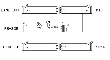
Figure 1 - Schematic Diagram
Click here to download the full PDF version of the instructions: SSCI.
How it works
The central idea is that the PC sound card is used as the modulator and demodulator for the
audio. To accomodate a different modulation technique or protocol only requires different
software. No hardware changes are required. Many different modes are now represented with sound
card versions. All the old favs, Packet (HF and VHF), AMTOR, PACTOR, RTTY, SSTV and many new ones
as well, PSK, Olivia, MT63, etc.
Parts Needed
The bill of materials is listed below. Theres nothing special about the parts, order them
from Mouser (cheaper) or buy from RS (expensive). You can eleminate the jacks, if you solder
the interface cables directly to circuitry. The audio transformer are for isolation and not
impedance matching. Use 600:600 line xformers, or whathave you, but pay attention to power
handling capability. This will imit the amount of audio from the radio or sound card that the
transformer core can handle before saturating. Running the core to saturation is a bad thing,
lots of spurious signals will be generated resulting in a trashy signal or transmit or bad
reception. Remember that the radio's speaker output is being used here, so there's lots of
audio power available. The simple fix is to turn down the volume!
The specified RS reed relay is good for this job as it's easy to energize. It requires
very little current to pull in, so a laptop or USB-2-Serial adapter should accomodate it
easily. Most designs I've seen around like to use an optocoupler to acheive the PTT function.
Well I tried that and had problems with about half the rigs I tried it on. It just flat
wouldn't key the radio. I switched to this relay and it's worked fine on every radio since.
I wouldn't key my SB-200 with it, but it will suffice for mobiles well enough.
The LED and resistor in series with the relay coil is really to provide a little voltage
dropping as most RS-232 outputs are 9-12 volts and the relay is designed for 5 VDC. The
amount of current required to energize the relay is about the same as whats needed to lite
an LED, so there ya go. Voltage dropping and indication in the same part. The LED can be any
color, theres no standard, but be aware that the resistor may have to be changed to accomodate
something different than green.
Bill of Materials:
| Qty |
Description |
Part # |
Ref Desg# |
| 3 |
3.5 mm Stereo Jack |
Any |
J1,2,4 |
| 2 |
3.5 mm Mono Jack |
Any |
J3,5 |
| 1 |
Reed Relay, 5V SPST |
RS 275-232Any |
K1 |
| 1 |
LED, T1-3/4, Green |
Any |
LED1 |
| 2 |
Transformer, Audio Isolation |
Any |
T1,2 |
| 1 |
Poly Project Box |
Any |
|
| 3 |
3.5 mm Stereo M-M Cables, ~3 ft |
Any |
J1,2,4 |
| 2 |
3.5 mm Mono M-M Cables, ~3 ft |
Any |
J1,2,4 |
Table 1 - Bill Of Materials
Here is a layout suggestion looking at the top of the project box. Holes for the connectors
and the LED can be started with a hot soldering iron and then filed to fit. Wiring is point to
point with the transformers wired directly to the jacks.
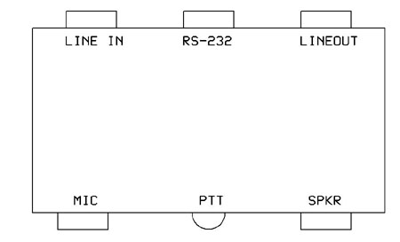
Figure 2 - Project Box Outline
Part two will include some assembly photos and the hookup and use of the interface.
Stay tuned....73's DE ~Steve>
|